Split clamp for a 25 mm pipe, two bolted halves
Measured on 2026-10-03. Every figure below is the kernel's, not an estimate.
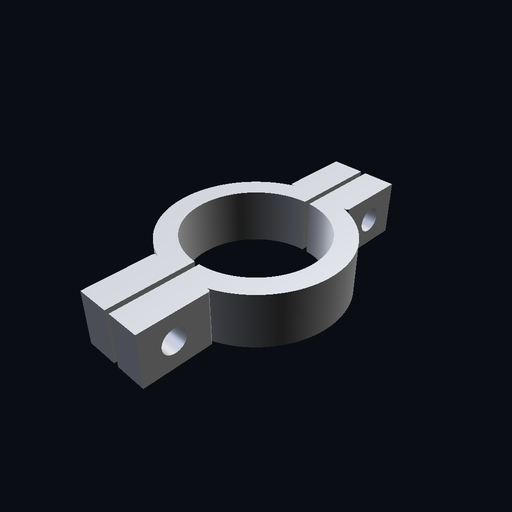
The prompt, as typed
A two-piece clamp for a 25 mm pipe: two half rings 10 mm wide, 4 mm wall, joined by two M4 bolts through tabs on each side, 1 mm gap between the halves when closed.
This part did not go through the design chat. It is case E16 of FITD's report eval, which sends the prompt straight to the pipeline as a paid-tier request: no clarifying question was asked, and there was no spec card for anyone to approve. The table below is the request exactly as the pipeline received it — the prompt, the process and the material — and nothing else.
The request the pipeline received
| description | A two-piece clamp for a 25 mm pipe: two half rings 10 mm wide, 4 mm wall, joined by two M4 bolts through tabs on each side, 1 mm gap between the halves when closed. |
| process | fdm |
| material | plastic |
Spec against measured
| Dimension | Spec | Measured | Result |
|---|---|---|---|
| split_gap clearance | 1.0 mm | 1.0 mm | Pass |
| pipe_bore bore Ø25 mm | 1, on the assembly | found 1 of 1 | Pass |
| half_ring Holes Ø4.5 mm | 2 per half | found 2 of 2 | Pass |
| half_ring pipe_bore share of Ø25 mm bore | 180° ± 5.5° | wraps 175.5° | Pass |
| Bounding box | — | 57.0 × 33.0 × 10.0 mm | Measured |
| Volume | — | 6,168.543 mm³ | Measured |
This is the clamp FITD's assembly verifier was rebuilt around. Earlier builds of this same request are why its rows exist: one came back as two correct halves composed back to back, every row green and no bore anywhere in it; another built a half whose bore wraps too far for two of them ever to close; a third named the bore in parameters the verifier could not read, so no bore was checked at all. Each of those is now a fixture in FITD's report eval. This run is case E16, run 201, of the report-eval run of 3 October 2026, with the case's prompt worded with a space between each number and its unit, and the eval's scoring found the report agreed with every assertion it makes about the case, with no false green. The pipeline read two identical half rings, so it built ONE part and placed it twice, and the report measured the composed pair as well as the half. The two placed solids intersect in 0.0 mm³, so the fit is clean. The gap between the halves measures 1.0 mm against the 1.0 mm asked for, inside a 0.2 mm tolerance. On the assembly the verifier looked for one Ø25 mm bore and found 1 of 1 — the row the back-to-back build could not have passed — and on the half it found both Ø4.5 mm clearance holes for the M4 bolts. The share-of-bore row is what tells a half that is placed wrong from a half that is the wrong shape: the half wraps 175.5° of the Ø25 mm bore against 180° ± 5.5°. The whole assembly measures 57 × 33 × 10 mm and 6,168.5432 mm³. The report also carries six bounding-box rows, three for the half and three for the pair, against sizes the planner estimated rather than sizes anyone asked for; they are marked "planner estimate — not graded", they decided nothing, and they are left off this page rather than shown as passes. No print-readiness wall figure and no render inspection are in this report, so neither is on the page. The two M4 bolts are bought, not printed. Print the half_ring STEP twice; the composed STEP is for checking the fit.
How a verification report is decided — what each status means, and a report that failed.
Also measured: Snap-lid box for SD cards, 80 × 50 × 30 mm, Cold-shoe adapter for a 1/4-20 tripod thread.
The files
The STL is the file the report above is about. The STEP is the same solid in an editable format, for when you want to change it in CAD later.
This part is an assembly, so the STEP above is the parts composed in their assembled positions — useful for checking the fit, not for printing. The per-part STEPs below are the pieces you print, and they are what the per-part rows were measured on.
Provenance
Generated through FITD’s own pipeline on 3 October 2026, as case E16 (run 201) of the report-eval run that day: the prompt at the top of this page went straight to the planner, the CadQuery build, the sandboxed kernel run and the measured assembly checks — the same ones a signed-in user gets — without the design chat in front of them, which is why there is no clarifying round and no approved spec card here. The composed STEP and the half_ring STEP offered above are the files that run produced: the half byte for byte, the composed STEP with one header line changed — its AI-generation marking reworded to the current form, which names no model, as on every demo file. Every figure in the table is the report that run stored. The STL is the composed STEP tessellated for this page with CadQuery; its volume agrees with the report’s to about a hundredth of a percent. The part is the operator’s own benchmark clamp, not anyone else’s design: no user’s part is ever published here.