Cold-shoe adapter for a 1/4-20 tripod thread
Measured on 2026-10-01. Every figure below is the kernel's, not an estimate.
The prompt, as typed
A cold-shoe adapter that mounts to a 1/4-20 tripod thread, standard 18.5mm shoe width
FITD asked: Could you confirm the overall envelope of the cold-shoe adapter? I'm assuming: a flat base block roughly 25mm (L) x 20mm (W) x 6mm (H), with a cold-shoe channel (18.5mm internal width, standard spring-clip profile) on top, and a 1/4-20 tapped hole centered on the bottom face for tripod mounting. Does this match what you need, or do you have specific dimensions in mind?
Answer: Base block 30 x 30 x 8 mm. Cold-shoe rails on top with 18.5 mm internal width, 2 mm rail overhang, rails 3 mm tall, open at one end. Not tapped: a plain 6.5 mm through hole centred in the base for a 1/4-20 bolt from below.
The spec that was approved
Nothing is generated, and no credit is charged, until this is agreed. Every field is editable before approval.
| part name | Cold-shoe tripod adapter |
| description | Flat rectangular base block with a cold-shoe mounting channel on top and a through-hole for tripod bolt mounting. The base is 30 x 30 x 8mm. On the top face, two parallel rails run along the full 30mm length, spaced to leave an 18.5mm internal channel width between them, each rail overhanging the channel by 2mm and standing 3mm tall, open at one end (not closed with an end-stop) to allow a cold-shoe accessory to slide in. A plain 6.5mm diameter through hole is centered in the base, passing vertically through the full 8mm height, sized to clear a 1/4-20 bolt inserted from below. Overall envelope: 30 x 30 x 11mm (8mm base + 3mm rail height). |
| base shape | box |
| process | fdm |
| material | plastic |
| wall thickness | 0 |
| notes | Rails are open at one end (no end-stop) to allow sliding insertion of a standard cold-shoe accessory; channel is 18.5mm internal width between rail inner faces. |
| dimensions | length 30 mm · width 30 mm · height 11 mm |
| features |
|
Spec against measured
| Dimension | Spec | Measured | Result |
|---|---|---|---|
| Width | 30.0 mm | 30.0 mm | Pass |
| Depth | 30.0 mm | 30.0 mm | Pass |
| Height | 11.0 mm | 11.0 mm | Pass |
| Holes Ø6.5 mm | at least one | found 1 | Pass |
| Volume | — | 8,078.843 mm³ | Measured |
| Minimum wall | — | 0.83 mm | Measured |
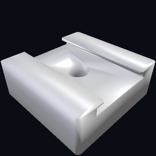
One clarifying round did the work on this one. "A cold-shoe adapter that mounts to a 1/4-20 tripod thread, standard 18.5mm shoe width" names the interface at both ends and nothing else: no block size, no rail height, no decision about whether the tripod screw threads into the part or passes through it. The question that came back proposed a 25 × 20 × 6 mm block and a tapped hole; the answer replaced both, and the spec that was approved is the answer's numbers — 30 × 30 × 8 mm base, rails 18.5 mm apart on the inside with 2 mm of overhang and 3 mm tall, open at one end, and a plain 6.5 mm through hole rather than a thread, because an M-sized thread printed in plastic at this scale strips and a bolt through a clearance hole does not. The report measured the envelope at 30 × 30 × 11 mm and found the Ø6.5 mm hole, and that is all it measured. Read the badge narrowly, which is how it is meant: no slot check was raised for the rail gap, so "verified" here is a claim about the bounding box and the hole, not about whether a flash will slide into the shoe. The numbers that decide that were measured for this page, on the same exported STL the download button hands you, and they are labelled as such rather than folded into the table as though the pipeline had produced them. The two rail inner faces are planes 59.00 mm² each at x = ±9.250 mm, so the channel between them is 18.500 mm wide. The two lip tips are planes 29.50 mm² each at x = ±7.250 mm, so the mouth is 14.500 mm and each lip overhangs the channel by 2.000 mm. The channel floor is a single flat plane at z = 8.000 mm and the underside of the lips sits at z = 10.000, with the top of the part at 11.000: a 2 mm slot under a 1 mm lip, rails 3 mm tall. The Ø6.5 mm bore runs from z = 0 to z = 8, through the base and no further, which is right — it has to come out in the channel floor, not through a rail. The render inspection filed two objections, both advisory and both wrong, in the same way the curtain-pole bracket's were: it read a dished, bowl-shaped channel floor around the hole, and it thought the rail ends tapered. Every vertex in that floor region of the mesh lies at exactly z = 8.000; the dish is smooth shading rolling the mesh normals over the rim of the hole. The report's thinnest measured span is 0.828 mm, just over the 0.8 mm FDM floor, at the chamfered lead-in where a shoe slides in. That one is real and worth knowing before you print: it is the lip, it is the part a spring clip pushes against, and 0.8 mm of PLA across the layers is not much. Printed flat with the channel upward it is fine; printed on its side it is a line of plastic waiting to split.
How a verification report is decided — what each status means, and a report that failed.
Also measured: M3 hex standoff, 15 mm tall, 5.5 mm across flats.
The files
The STL is the file the report above is about. The STEP is the same solid in an editable format, for when you want to change it in CAD later.
Provenance
Generated through FITD’s own pipeline on 1 October 2026 from the prompt and the one clarifying round at the top of this page, and verified on the first build. The badge covers what the report measured: the envelope, the Ø6.5 mm hole and the print-readiness pass. The 18.5 mm rail gap, the 2.000 mm lip overhang, the channel floor at z = 8.000 and the flatness of that floor were measured for this page, by hand, on the STL offered above — which is the run’s own file, byte for byte — and they are stated as page-side measurements rather than added to the report’s rows, because the pipeline did not make those claims. The part is the operator’s own benchmark adapter, not anyone else’s design: no user’s part is ever published here.