Snap-lid box for SD cards, 80 × 50 × 30 mm
Measured on 2026-10-01. Every figure below is the kernel's, not an estimate.
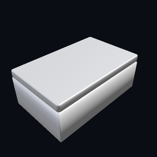
The prompt, as typed
A small box with a snap-on lid, 80mm by 50mm by 30mm outside, 2mm walls, for storing SD cards.
FITD asked: How should the lid attach — a lip rim around the top edge of the base with a snap-fit lid that overlaps it, and should the lid be a shallow cap (a few mm tall) or flush with the box height? Also, do you want any internal dividers/slots for SD cards, or just an open compartment?
Answer: Lip rim around the top edge of the base, with a shallow snap-fit cap lid about 5 mm tall that overlaps the lip, so the assembled box is still 80 x 50 x 30 mm outside. One row of SD card slots along the 80 mm length, 26 mm across the width, centred, 20 mm deep.
The spec that was approved
Nothing is generated, and no credit is charged, until this is agreed. Every field is editable before approval.
| part name | SD card snap-lid box |
| description | Small storage box with snap-on lid for SD cards. Base is an open-top box 80x50x30mm outside with 2mm walls, with a narrow lip rim protruding around the top inner edge for the lid to snap onto. Lid is a shallow cap, 5mm tall, that fits over the base lip via snap fit, sized so the assembled closed box remains 80 x 50 x 30mm outside overall (lid height counts within the total 30mm, base height is 25mm plus 5mm lid). Inside the base, a row of card slots runs along the 80mm length: a rectangular pocket 26mm wide (centred across the 50mm width), 20mm deep, milled/printed into the base interior to hold SD cards upright in a line. Overall envelope: 80 x 50 x 30 mm (base + lid combined, as specified by user). |
| base shape | box |
| process | fdm |
| material | plastic |
| hollow | true |
| wall thickness | 2 |
| open faces | top |
| assembly | [object Object] |
| dimensions | length 80 mm · width 50 mm · height 30 mm |
| features |
|
Spec against measured
| Dimension | Spec | Measured | Result |
|---|---|---|---|
| Base width | 80.0 mm | 80.0 mm | Pass |
| Base depth | 50.0 mm | 50.0 mm | Pass |
| Base height | 25.0 mm | 25.0 mm | Pass |
| Lid width | 80.0 mm | 80.0 mm | Pass |
| Lid depth | 50.0 mm | 50.0 mm | Pass |
| Lid height | 5.0 mm | 5.0 mm | Pass |
| Assembly width | 80.0 mm | 80.0 mm | Pass |
| Assembly depth | 50.0 mm | 50.0 mm | Pass |
| Assembly height | 30.0 mm | 30.0 mm | Pass |
| Snap-lip clearance | 0.30 mm | 0.35 mm | Pass |
| Parts built and measured | base + lid, as the contract names them | 2 of 2 built, both exported | Pass |
| Interfaces checked | snap_lip, closed_height | 2 of 2 checked | Pass |
| Base/lid interference | no overlapping material | 0.00 mm³ intersection — fit clean | Pass |
| Volume | — | 31,241.794 mm³ | Measured |
This is a two-part assembly, and it is the first example on this site whose first build did not pass. The prompt at the top asked for an 80 × 50 × 30 mm box with 2 mm walls and a snap-on lid. One clarifying round settled the two things the sentence left open — how the lid attaches and whether the inside is divided — and the approved spec came back as a base and a lid: an open-top box 25 mm tall with a lip rim and a 26 × 20 mm card pocket, plus a 5 mm cap that snaps over the lip, so that closed the whole thing is still 30 mm tall. Before anything was generated, a contract was written down for the pair: base 80 × 50 × 25, lid 80 × 50 × 5, and a snap_lip interface carrying a 1.5 mm lip, a 0.8 mm hook and 0.3 mm of lateral clearance per side. Then the first build was measured against that contract and two rows came back red. The base measured 26.5 mm tall where the contract said 25.0, and the snap lip measured 0.00 mm of clearance where the contract said 0.30 — a lid that would have had to be forced on, and a closed box that no longer added up. The report stored for that build said best effort and named both rows; nothing was hidden and nothing was rounded towards the spec. Pressing "Fix these in a refinement" did not start a negotiation about what the part should be. The contract already stated the right numbers, so the two affected parts were rebuilt against it and measured again, and because the error was the build's and not the specification's, no new credit was charged. The re-measure is the table above: base 80 × 50 × 25, lid 80 × 50 × 5, assembly 80 × 50 × 30, snap-lip clearance 0.35 mm against the 0.30 mm the contract asked for, and the boolean check between the two solids finds 0.00 mm³ of shared material, so the lid seats without interfering. That is what the badge means here: not that the part passed first time, but that it is passing now and the record says how it got there. For comparison, the curtain-pole bracket is an example that passed its measurements on the first build; this one did not.
How a verification report is decided — what each status means, and a report that failed.
Also measured: Wall bracket for a 32 mm curtain pole.
What the first build measured
These are the measurements of the build this one replaced — stored as they came out, on geometry that no longer exists. The rows marked Fail are why there was a correction round at all.
| Dimension | Spec | First build | Result |
|---|---|---|---|
| Base width | 80.0 mm | 80.0 mm | Pass |
| Base depth | 50.0 mm | 50.0 mm | Pass |
| Base height | 25.0 mm | 26.50 mm | Fail |
| Lid width | 80.0 mm | 80.0 mm | Pass |
| Lid depth | 50.0 mm | 50.0 mm | Pass |
| Lid height | 5.0 mm | 5.0 mm | Pass |
| Assembly width | 80.0 mm | 80.0 mm | Pass |
| Assembly depth | 50.0 mm | 50.0 mm | Pass |
| Assembly height | 30.0 mm | 30.0 mm | Pass |
| Snap-lip clearance | 0.30 mm | 0.0 mm | Fail |
Refinements
Fix the verification failures: base height measured 26.5 mm, spec 25.0 mm; snap_lip clearance measured 0.0 mm, spec 0.3 mm. The verification report noted: "base height 26.5mm, expected 25.0mm. snap_lip clearance 0.00mm, expected 0.30mm". Keep every dimension that passed unchanged.
Parts were rebuilt to match the stored contract and re-measured, at no new charge. Base and lid were both affected; every row passed on the re-measure and the stored status went from best effort to verified after correction.
The files
The STL is the file the report above is about. The STEP is the same solid in an editable format, for when you want to change it in CAD later.
This part is an assembly, so the STEP above is the parts composed in their assembled positions — useful for checking the fit, not for printing. The per-part STEPs below are the pieces you print, and they are what the per-part rows were measured on.
Provenance
Generated through FITD’s own pipeline on 1 October 2026 from the prompt at the top of this page, and corrected by FITD’s own measurement loop: the first build’s base height and snap-lip clearance were caught by the kernel measuring the solid against the stored assembly contract, not by anyone looking at it, and the rebuild was measured the same way. The part is the operator’s own benchmark box, not anyone else’s design: no user’s part is ever published here. The STL, the composed STEP and the two per-part STEPs offered above are the files that run produced, byte for byte, and every figure in both tables was measured on them.