Wall bracket for a 32 mm curtain pole
Measured on 2026-09-27. Every figure below is the kernel's, not an estimate.
The prompt, as typed
A wall bracket for a 32mm curtain pole, two 5mm screw holes, holds the pole 60mm from the wall.
FITD asked: Can you confirm the general shape: a flat wall-mount plate with two screw holes, connected to a semi-circular (U-shaped) cradle that cups the 32mm pole, projecting 60mm out from the wall? Also, roughly what size should the mounting plate be (e.g. 40mm wide x 80mm tall), and how thick should the bracket arm/plate be (e.g. 5mm)?
Answer: Flat back plate with a top-open U cradle the pole drops into. 20 mm wide, arm 5 mm thick, back plate 60 × 40 × 5 mm, screw holes 40 mm apart on the centreline.
The spec that was approved
Nothing is generated, and no credit is charged, until this is agreed. Every field is editable before approval.
| part name | Curtain pole wall bracket |
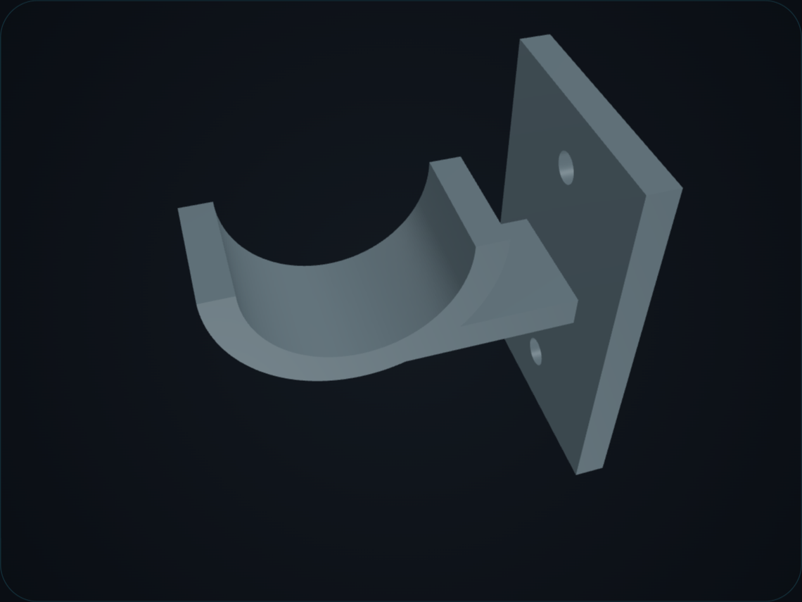
| description | Wall-mounted curtain pole bracket, FDM printed plastic. Flat rectangular back plate 60mm (H) x 40mm (W) x 5mm thick, mounted flush to the wall, with two clearance screw holes 40mm apart on the vertical centreline for wall fixing. Projecting perpendicularly from the plate is a 20mm wide support arm, 5mm thick, extending 60mm from the wall face to position the pole's centre at that distance. The arm terminates in a top-open U-shaped cradle (semi-circular, open at the top) sized to cup a 32mm diameter pole, into which the pole drops from above. |
| base shape | box |
| interface fit | Cradle cups a 32mm diameter curtain pole, 0.5mm clearance (cradle radius 16.25mm) so the pole drops in from the top and rests freely. |
| process | fdm |
| material | plastic |
| wall thickness | 5 |
| tolerances | ±0.2mm |
| notes | Back plate 60x40x5mm flush to wall; arm 20mm wide x 5mm thick projects 60mm from plate to cradle centre. Sharp edges except the cradle radius. |
| dimensions | length 60 mm · width 40 mm · height 60 mm |
| features |
|
Spec against measured
| Dimension | Spec | Measured | Result |
|---|---|---|---|
| Width | 60.0 mm | 60.0 mm | Pass |
| Depth | 40.0 mm | 40.0 mm | Pass |
| Height | 60.0 mm | 60.0 mm | Pass |
| Ø5 mm screw holes | 2 | 2 of 2 found, Ø5 mm | Pass |
| Cradle bore | Ø32.5 mm (32 mm pole + 0.5 mm) | Ø32.5 mm | Pass |
| Cradle opening | at least 150° open | 180° open | Pass |
| Volume | — | 19,933.5 mm³ | Measured |
| Minimum wall | — | 4.39 mm | Measured |
The kernel measured all three stated dimensions exactly — 60 × 40 × 60 mm — and the feature checks find both Ø5 mm screw holes, a Ø32.5 mm cradle bore and 180° of open arc over the top of it, so the pole drops in from above. The thinnest wall the print-readiness sampler found is 4.39 mm against a 5 mm nominal; that is the smallest span anywhere in the solid, not a plate thickness. The report stored on 27 September 2026 did not say verified. It said best effort, because the render inspection looked at the four rendered views and objected three times: it read the flat back plate as a faceted pyramid, thought the arm narrowed part-way along, and found only one screw hole in the right-hand view. None of those objections is in the solid. The renders smooth-shade a coarse triangle mesh, which rounds the sharp edges of a 5 mm slab into something that looks moulded; that is where the pyramid and the waist came from. The missing hole was simply not missing. Measuring the exported STEP gives a flat plate, a constant-section arm and two holes. The renders were wrong and the measurement was right, which is why measurements decide the badge and a render inspection can only add a second opinion on top of them. The badge above is the re-measured verdict; the badge stored on the day is written out here rather than quietly replaced.
How a verification report is decided — what each status means, and a report that failed.
The files
The STL is the file the report above is about. The STEP is the same solid in an editable format, for when you want to change it in CAD later.
Provenance
Generated through FITD’s own pipeline on 27 September 2026 from the prompt at the top of this page — the chat, the spec approval, the CadQuery build, the sandboxed kernel run and the report are all the ones a signed-in user gets. The part is the operator’s own benchmark bracket, not anyone else’s design: no user’s part is ever published here. The STEP and STL offered above are the files that run produced, byte for byte, and every figure in the table was measured on them.