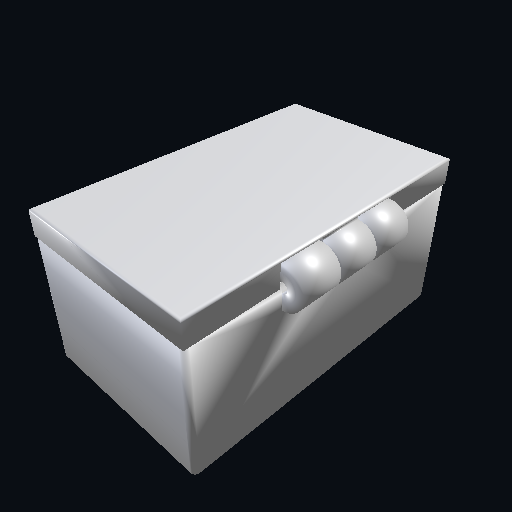
Hinged box, 60 × 40 × 30 mm, base and lid on a pin hinge
Measured on 2026-10-08. Every figure below is the kernel's, not an estimate.
The prompt, as typed
A two-part hinged box 60mm by 40mm by 30mm, base and lid, 2mm walls, joined along one long edge by a pin hinge.
Nothing was ambiguous, so nothing was asked.
The spec that was approved
Nothing is generated, and no credit is charged, until this is agreed. Every field is editable before approval.
| assembly | [object Object] |
| base shape | box |
| description | Two-part hinged storage box. Base is an open-top box 60 x 40 x 30 mm with 2mm walls, hollow interior, forming the main storage volume. Lid is a shallow box that caps the base, overlapping the wall tops with a 0.3mm clearance inner lip for location. The two parts are joined along one long top edge by a 3-knuckle pin hinge (2 knuckles on base, 1 on lid, Ø2mm bore), with a loose filament pin (1.75mm diameter) pushed through after printing. Hinge opens to 90°. Overall envelope: 60 x 40 x 30 mm as stated by the user (closed product, base bounding box used as primary body). |
| hollow | true |
| material | plastic |
| open faces | top |
| part name | Hinged storage box |
| process | fdm |
| wall thickness | 2 |
| dimensions | length 60 mm · width 40 mm · height 30 mm |
Spec against measured
| Dimension | Spec | Measured | Result |
|---|---|---|---|
| assembly width | 60.0 mm | 60.0 mm | Pass |
| assembly depth | 40.0 mm | 40.0 mm | Pass |
| assembly height | 30.0 mm | 30.0 mm | Pass |
| assembly body height | 30.0 mm | 30.0 mm | Pass |
| lid_hinge clearance | 0.25 mm | 0.25 mm | Pass |
| lid_lip clearance | 0.30 mm | 0.0 mm | Fail |
| lid_hinge bore Ø2 mm | 1, on the assembly | found 1 of 1 | Pass |
| lid_hinge bores coaxial | one axis, within 0.15 mm and 2° | 0.00 mm apart, 0.0° | Pass |
| lid_hinge knuckles interleave | alternating, gaps 0.40 ± 0.15 mm | alternating, gaps 0.40 mm | Pass |
| lid_hinge opens to 90° | 90° ± 5° | free to 90°, 18 steps of 5° | Pass |
| lid_lip assembles | lifts off along +Z, fully free | clear over 8.5 mm | Pass |
| lid_lip lid covers the base | covers the base's outer edge on every side | 60.0 × 40.0 covers 60.0 × 36.0, largest inset 0.0 mm | Pass |
| Bounding box | — | 60.0 × 40.0 × 30.0 mm | Measured |
| Volume | — | 24,767.19 mm³ | Measured |
This is the hinged box on FITD's landing page, generated on 8 October 2026 through the design chat: the prompt above went in, nothing in it was ambiguous, and the spec card came back in the same chat and was approved. The planner read it as two printed parts — an open-top base and a lid — joined along the rear long edge by a three-knuckle pin hinge, two knuckles on the base and one on the lid, with a 1.75 mm filament pin pushed through after printing. The pin is stated, not modelled, so the 0.25 mm hinge clearance is measured from the Ø2 mm bore against the stated pin. The report measured the composed assembly as well as each part. The two placed solids intersect in 0.0 mm³, so the fit is clean. Closed, the box measures 60.0 × 40.0 × 30.0 mm against the 60 × 40 × 30 mm asked for, and the closed body without the hinge knuckles is 30.0 mm tall. On the hinge the verifier found the Ø2 mm bore, measured the base's and the lid's bores 0.00 mm apart on one axis along X at y 36, z 25, found the knuckles alternating with 0.40 mm gaps, and swung the lid about that axis in 18 steps of 5° to 90° without it entering the base. The lid lifts off along +Z clear of the base over 8.5 mm, and its 60.0 × 40.0 mm footprint covers the base's 60.0 × 36.0 mm outer edge on every side. The one failing row is the locating lip under the lid: the spec asked for 0.3 mm of clearance between the lip and the inside of the base walls, and the kernel measured 0.00 mm. One automatic correction round rebuilt both parts and measured the same 0.00 mm, so the original was kept and the badge says Best effort. The report also carries six per-part bounding-box rows against sizes the planner estimated rather than sizes anyone asked for; they are marked "planner estimate — not graded", they decided nothing, and they are left off this page rather than shown as passes. The bore-and-pin fit row in the report is the same 0.25 mm measurement as the lid_hinge clearance row above, so it is printed once. No print-readiness wall figure and no render inspection are in this report, so neither is on the page. Print the base and lid STEPs (or STLs); the composed files are for checking the fit.
How a verification report is decided — what each status means, and a report that failed.
Also measured: Snap-lid box for SD cards, 80 × 50 × 30 mm, Split clamp for a 25 mm pipe, two bolted halves.
The files
The STL is the file the report above is about. The STEP is the same solid in an editable format, for when you want to change it in CAD later.
This part is an assembly, so the STEP above is the parts composed in their assembled positions — useful for checking the fit, not for printing. The per-part STEPs below are the pieces you print, and they are what the per-part rows were measured on.
Provenance
Generated through FITD’s own pipeline on 8 October 2026 through the design chat, from the prompt at the top of this page: no clarifying question was asked, and the spec card above is the one that came back and was approved. The planner, the per-part builds, the sandboxed kernel run, the measured assembly checks and the one correction round are the ones a signed-in user gets. The composed STEP and the base and lid STEPs offered above are the files that run produced, byte for byte, and every figure in the table is the report that run stored. The three STLs are those STEPs tessellated for this page with CadQuery at the product’s own print settings; their volumes agree with the report’s to within a thousandth of a percent. The part is the operator’s own benchmark box, not anyone else’s design: no user’s part is ever published here.