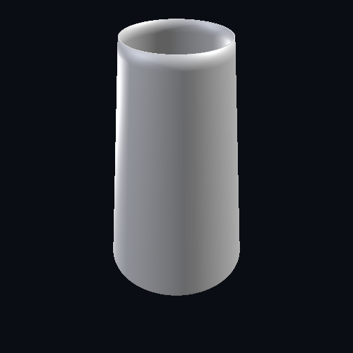
Tapered vase, 100 mm tall, 0.5 mm walls
Measured on 2026-10-01. Every figure below is the kernel's, not an estimate.
The prompt, as typed
A vase 100mm tall with 0.5mm walls.
FITD asked: 0.5mm walls are below the recommended FDM minimum of 1.6mm, which risks poor layer adhesion and leaks. I'll bump this up to 1.6mm unless you prefer otherwise—also, what diameter should the vase be? What diameter should the vase be (top and bottom — same, or tapered)? Also, 0.5mm walls are far below the FDM minimum of ~1.6mm and likely won't print reliably — okay if I set wall thickness to 1.6mm instead?
Answer: Keep the walls at 0.5 mm, I want to see what the print check says. 60 mm diameter at the base tapering to 40 mm at the top, open top, 3 mm floor.
The spec that was approved
Nothing is generated, and no credit is charged, until this is agreed. Every field is editable before approval.
| part name | Tapered vase |
| description | Decorative open-top vase, cone-shaped, tapering from 60mm diameter at the base to 40mm diameter at the top. Hollow with 0.5mm wall thickness (user explicitly requested, below typical FDM minimum of 1.6mm — may not print reliably) and a 3mm solid floor. Top face is open. Overall envelope: 60 x 60 x 100 mm (diameter at widest point = base, height = 100mm). |
| base shape | cone |
| hollow | true |
| wall thickness | 0.5 |
| open faces | top |
| process | fdm |
| material | plastic |
| purpose | Decorative vase for holding flowers or as a standalone ornament. |
| notes | Floor thickness is 3mm (solid base before hollow cavity begins). Wall thickness of 0.5mm is intentionally below the FDM minimum of 1.6mm per user request to test print-check behavior. |
| dimensions | bottom_diameter 60 mm · top_diameter 40 mm · height 100 mm |
Spec against measured
| Dimension | Spec | Measured | Result |
|---|---|---|---|
| Width | 60.0 mm | 59.79 mm | Pass |
| Depth | 60.0 mm | 59.79 mm | Pass |
| Height | 100.0 mm | 100.0 mm | Pass |
| Minimum wall thickness | 0.80 mm | 0.50 mm | Fail |
| Volume | — | 15,880.855 mm³ | Measured |
This is the second kind of failed report on this site, and it is the more interesting one. The SD-card box failed because the build missed the specification and was corrected. This vase failed because the specification itself will not print, and nothing was corrected, because there was nothing wrong to correct. The prompt was four words of shape and one impossible number: a vase 100 mm tall with 0.5 mm walls. The chat said so before anything was generated — 0.5 mm is below the FDM minimum, it risks poor layer adhesion and leaks, and it offered to raise the wall to 1.6 mm. The answer was to keep 0.5 mm deliberately, and to add the three things the prompt had not said: 60 mm at the base tapering to 40 mm at the top, open top, 3 mm floor. The spec that was approved carries the 0.5 mm wall with the warning written into its own notes, which is the only honest way to record a number someone insisted on. Then it was built and measured. The envelope is right: 59.79 × 59.79 mm across a nominal 60 (the cone is tessellated into facets, and a flat-to-flat measurement across a faceted circle is fractionally under its true diameter), and 100.00 mm tall exactly. Re-measuring the STL here gives the same figures, a floor plane at exactly z = 3.000 mm, and at the rim an outer radius of 20.0000 against an inner radius of 19.4975 — a 0.5025 mm wall. The print-readiness pass measures a wall perpendicular to the surface rather than horizontally, and the outer wall leans 5.711° off vertical over its 100 mm, so 0.5 mm of horizontal wall is 0.5 × cos 5.711° = 0.4975 mm thick where it counts. The check reported 0.496 mm against a floor of 0.8 mm and failed it. Sampling the same way on the exported file here gives 0.4966 mm. So every number agrees with every other number, the part is exactly what was asked for, and it is not printable: at 0.5 mm a 0.4 mm nozzle lays a single bead with nothing to bond to on either side, and a 100 mm tall cone of single beads is a shape that exists in a file and collapses on a bed. What did NOT happen is the part worth noticing. There is a fix loop that re-builds a part when a measurement disagrees with the contract, and it did not run. It had nothing to do: no measured dimension disagrees with the spec, so there is no build error to correct, and the thing standing between this file and a finished vase is a decision that was made in the chat with the consequence stated at the time. A fix loop that "corrected" this one would have quietly overwritten the number the request was actually about. Best effort, with the failing row printed and the reason beside it, is the only report that tells the truth here. If you want this vase to print, the fix is a sentence, not a rebuild: ask for the same shape with a 1.6 mm wall, or print it in vase mode, where the slicer deliberately runs a single continuous bead and the 0.8 mm floor does not apply because nothing is trying to be solid.
How a verification report is decided — what each status means, and a report that failed.
Also measured: Snap-lid box for SD cards, 80 × 50 × 30 mm.
The files
The STL is the file the report above is about. The STEP is the same solid in an editable format, for when you want to change it in CAD later.
Provenance
Generated through FITD’s own pipeline on 1 October 2026 from the prompt at the top of this page, including the exchange where the chat warned that a 0.5 mm wall is below the FDM minimum and the answer was to keep it. Both turns are quoted above as they were sent. The table is the report that run stored, failing row and all; no refinement was requested and none ran. The confirming figures in the note — the 0.5025 mm wall at the rim, the 5.711° lean and the 0.4966 mm perpendicular span — were measured for this page on the STL offered above, which is that run’s file byte for byte. The part is the operator’s own benchmark vase, not anyone else’s design: no user’s part is ever published here.