FITD
Files you can trust enough to print
Describe a part in plain English. Get STEP and STL back, measured against your spec.
Invite-only beta — free while in beta.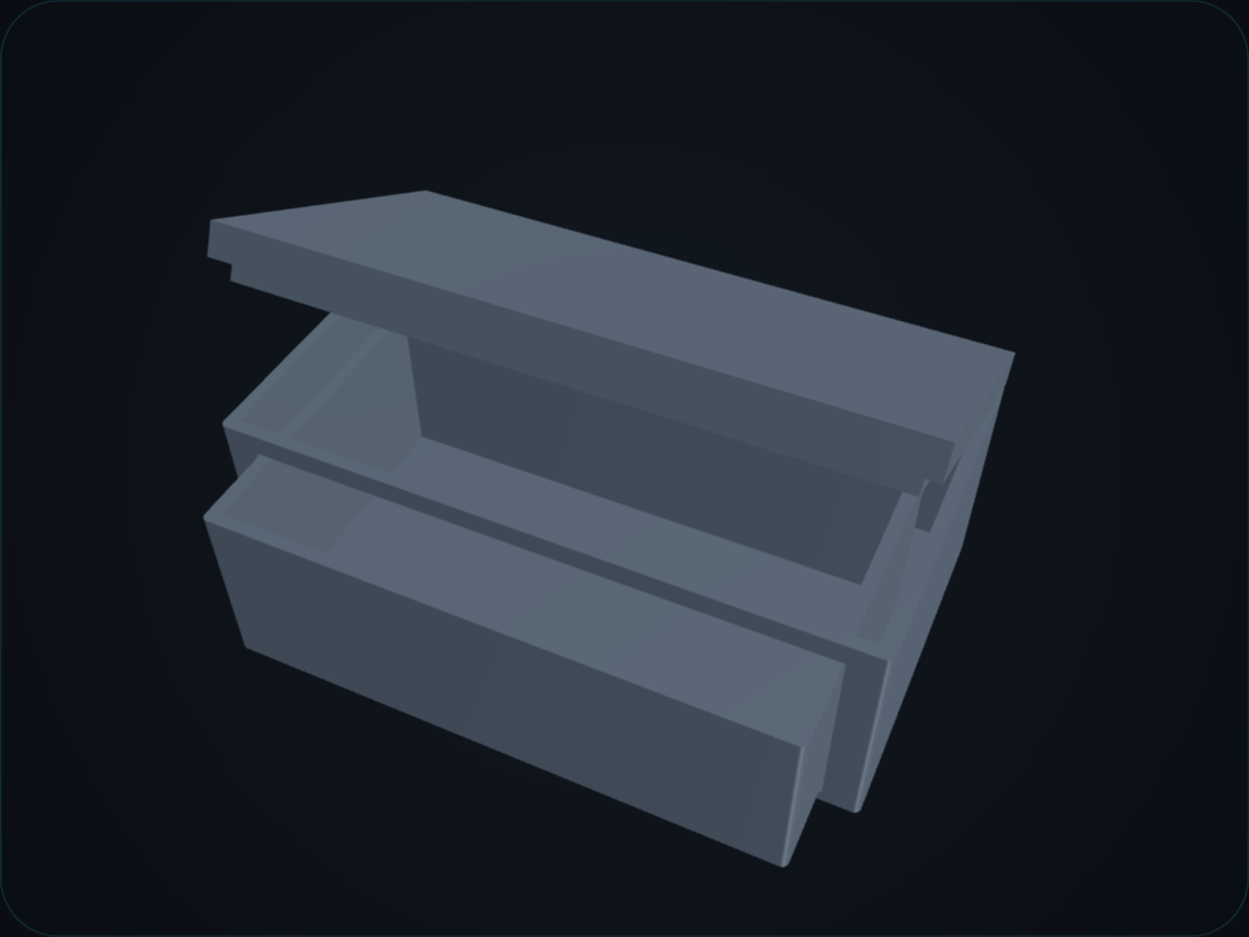
Verification
Verifiedspec 100.0 mm · measured 100.0 mm
spec 60.0 mm · measured 60.0 mm
spec 40.0 mm · measured 40.0 mm
spec 0.3 mm · measured 0.3 mm
spec 90° · measured 90°
spec 52.0 mm · measured 52.0 mm
79.8 cm³
An assembly is not several parts in a folder — it's the agreements between them. Describe a box with a snap-on lid, or a knob and its insert, and you get two to five parts designed together from that one description: each part generated and measured on its own, then composed and checked against the others so the mating faces actually clear. Where they don't, the fit is corrected and the correction is reported, or the conflict is flagged.
Two to five parts, designed together and checked against each other.
Two to five parts, one description
The parts list and the numbers the parts must agree on — shaft diameters, clearances, bolt patterns — are worked out first and shown to you to edit and approve before anything is charged. One credit per part, so the price tracks the work.
Fit is measured, not assumed
Each part is measured against its own dimensions, the same way a single part is. Then the positioned parts are intersected in the geometry kernel: overlap has to measure as good as zero. A mis-seated part is re-seated and the report says by how much; a real conflict is named, with the parts and the axis. A fit problem is not shipped quietly.
Every part on its own terms
An exploded view in the browser shows how it goes together, and each part has its own STEP and STL alongside the assembled STEP. Change one part's dimensions later and only that part is rebuilt, then the set is recomposed and re-checked.
If you've spent any time in the printing community lately, you know the problem: generated models with impressive renders that turn out to be non-manifold, mis-sized, or physically impossible — discovered two hours into the print. FITD's position is simple: a file you can't check is a file you can't trust. So every part comes with its receipts.
A file you cannot check is a file you cannot trust — so every part comes with its receipts.
Dimensional check
A geometry kernel measures the actual output file. Not "the model was told to make it 32mm" — measured, from the geometry itself.
Visual inspection
The generated geometry is rendered and inspected automatically. What you preview is the actual file, not a concept render.
Honest failure
If a part can't be verified against your spec — or two parts of an assembly won't clear each other — the report says so. You're never handed a plausible-looking file and left to discover the problem on the print bed.
What it won't do
The limits, stated plainly, before you spend an invite on it.
No decorative or organic models
No figurines, no sculpts. This is for functional parts, and sculpted or artistic surface modelling isn't what it does.
Assemblies stop at five parts
No sub-assemblies yet. Hinges, slides, snaps, threads, gears and four-bar linkages are swept in the geometry kernel and animated in the viewer from the measured motion, but that is a geometric check, not a physics simulation: nothing here predicts load, wear or spring-back.
Redesigns are new parts.
You can refine a single part in the chat and change an assembly's dimensions part by part; a change that breaks a mating fit shows up in the report as interference or a failed fit row. Describing a wholesale redesign of an existing assembly in chat is not supported yet.
Only what the card states is checked.
Every feature on the approved spec card is measured or marked 'not measured', and anything not measured withholds the green badge. A feature you had in mind but did not put on the card is not checked, so read the card before you approve it.
Not certified for safety-critical use
The verification confirms the geometry matches your spec, not that the part is fit for any particular purpose. That judgement stays with you — generated parts should not be used in safety-critical applications without professional review.
Honest FAQ
What can it actually make?
Functional parts: brackets, mounts, knobs, jigs, spacers, clips, enclosure-type shapes, adapters. The stuff you'd otherwise learn CAD for or ask a forum to model. And multi-part assemblies of two to five parts — a base and a snap-on lid, a knob and its insert — from one description. Verification is measured against a ladder of 236 real prompts, audited independently after each pass: zero false greens across the last two passes. The verifier is versioned and every report says which version judged it.
Can it do multi-part assemblies?
Yes — two to five parts from a single description. The parts and the numbers they have to agree on (shaft diameters, clearances, bolt patterns) are worked out first and shown to you to edit and approve before anything is charged. Each part is then generated and measured on its own, the parts are positioned together, and the overlap between mating parts is measured in the geometry kernel. You get an exploded view in the browser, a STEP and STL for every part plus the assembled STEP, and one credit is charged per part.
What mechanisms does it understand?
Hinges with pin bores and knuckles, sliding lids and trays with retention, snap-fit lids with measured arm strain and engagement, modelled or called-out threads to ISO and jar standards, spur gear pairs with a meshing sweep, ratchets, detents and latches, four-bar linkages, and screw bosses with heat-set inserts or self-tapping pilots from a sourced table. Each comes with its own measured rows and, where it moves, an animation of the measured motion.
What files do I get?
STEP and STL. STEP so you can modify it in real CAD later if you want; STL so you can slice it now. For an assembly, a STEP and STL for each part plus a STEP of the whole thing assembled.
What does it cost?
The beta is free — invites come with roughly 20 generation credits. A single part costs one credit; an assembly costs one per part, so a three-part assembly is three. Paid pricing after beta isn't decided yet, and we'd rather not guess at it here.
Who's behind this?
One person, with a background in materials science and manufacturing engineering. That means the manufacturability rules — wall thicknesses, hole tolerances, overhangs — are informed by real practice. And when you send feedback, the person who reads it is the person who fixes it.
What happens to my descriptions and files?
They're yours. Nothing you generate is published anywhere without you choosing to share it.